

‘Pipe Dream’: useful for passing time in the late 1980s, not that useful for planning livestock systems.
One of our key milestones in the development of the property this year was the establishment of a watering system for livestock. Having a watering system supports our fencing of the farm dam and waterways for habitat regeneration and also allows us to more intensively manage the movement and impact of livestock through rotational grazing. While we’re still the furthest thing from expert, with the advice and support of our neighbours, we managed to knock together a watering system that works. In researching and developing our own plans, we found an absence of basic information on setting up stock systems, so the ideas below are a few of the things we learnt or found useful in planning a system for our own context and landscape. They are just one perspective in informing your own planning, and shouldn’t be read as an endorsement of any particular way of doing things.
Research and Planning
From the beginning we wanted our stock watering system to be largely gravity-fed. This would mean we could pump up to tanks from the dam during times of rainfall abundance, and then feed livestock troughs positioned at lower elevations throughout the hotter months. Using online altitude finders and walking around the block, we worked out two high points from which to pump from the dam, and began to sketch up plans. We placed our proposed pipelines along present or proposed future fencelines to minimise the amount of vehicle and stock traffic crossing them. We then drafted our plan in Naturemaps, allowing us to measure approximate pipe lengths, explore different trough locations according to fencelines and topography and visualise the plan against aerial imagery of the property itself.
We found little useful information on the basics of setting up a stock watering system online, so we talked to as many people as we could about our ideas, from pump and tank vendors to the staff at the local ag-store. The advice of our neighbours Rob and Pamela were especially invaluable for this. Rob was enormously generous with his time and insight, touring us around his property to talk through his thinking in setting up his own system, and fielding our questions with patience.
Pumps In working out the best pump for our needs, we initially explored both solar and wind options, but found their price puts them firmly in the “maybe-in-the-future” category. We settled on a petrol-powered fire pump, as this allows us to top up the tanks with occasional, high-intensity bursts, offers the flexibility of using it all over the property, is a fraction of the cost of the other systems and we can even use it to fight fires!
Tanks From our research, steel and poly tanks have about the same lifespan, with steel having the benefit of being more readily recyclable at the end of its useful life. That said, we chose poly tanks for several reasons, among them their lower price, greater ease of maneuvering with human power, and less engineering required in constructing pads to support their weight. We chose poly troughs as well, for the same reason of being able to move them easily thus supporting flexibility in the system.
Once we had what we thought was a pretty good plan, we showed it to the local agricultural supplies store where we were purchasing our pipes, tanks and fittings. They promptly told us that we’d gotten a bit carried away, and stripped back the plan to something more minimal and functional. We then thought about it a bit more and made a few more changes until it was something we were happy with. Something I struggled with was trying to work out where valves were necessary to regulate flow in a gravity-based system. To their credit, the ag-store allowed us to take and return fittings over the couple of days while we were building the system, allowing us to experiment until we had it right.
Setting up tank pads
One of the benefits of poly tanks is their relative lightness and maneuverability. This is great for supporting flexibility in the plan as an empty tank can be moved without the need for a crane or truck. While a concrete base is often recommended for the weight of steel tanks, poly tanks can be supported with a less engineered pad. Tank manufacturers typically recommend a pad that is a minimum of 600mm wider than the diameter of the tank (300mm on each side), filled with dolomite or crusher dust 75-100mm thick. For a tank with a diameter of 3.6m (22,500L), we opted to build a timber square, 4.2m on each edge.

Pad #1: The dig-in-the-edges option

Pad #2: The flatten-it-with-a-tractor option. A bonus of this is that is allowed us to use the excess soil to construct a berm on contour above the pad, supporting rainwater harvesting and future plantings.
For our first pad, we constructed the square, using 100mm screws in the corners and supported by corner plates on the inside edge, then dug out the edges so the square frame sat level. While the ground level inside the frame was not level, at its highest, it was still 75mm below the top edge of the frame. For the second frame, we used the front bucket of the tractor to scrape out a level area, then placed the timber frame on top, with only minimal adjustments required. We fixed the frames in place by knocking galvanised rebars into the ground on the outside edge of the frame, securing them to the timber with copper plumber’s clips. A bit more blingy than intended, but it does the trick.

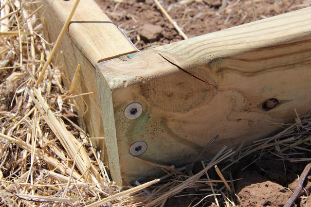
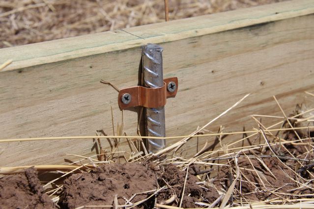
Tank-pad bling: The rebar and plumber’s clip fixing option. It’s a good idea to knock the rebar to just below the surface of the timber to avoid it piercing the tank when it’s unloaded.
We calculated each pad would need about 1.75 cubic metres of dolomite, or 3.5 tonnes (the local landscape guy said there’s about 2 tonnes to the cubic metre for dolomite). We had it delivered, raked it into place, then flattened and levelled it by running a plank of wood across the top using the timber edge of the pad as a guide.

Dolomite, levelled, ready.
Pipes: The bottom bit
At the dam end of the system, we set up an intake using 2 inch (50mm) rural greenline pipe connected to the fire pump. We fitted the intake pipe with a foot-valve to go in the water (a foot valve only allows water to flow in, but not back out of the system), and wrapped it in flyscreen held in place with cable-ties, as an extra filter against bugs and sediment. Ideally, we wanted to keep the intake off the bottom of the dam to avoid sucking in sediment, but about 20cm below the surface to avoid sucking in air. We initially wired an empty juice bottle to the end of the pipe to act as a float for when the pipe filled with water and began to sink, however, the rigidity of the pipe meant it kept trying to surface despite its weight. I ended up wiring a rock to the intake to pull it down, then threaded timber underneath it to give it enough buoyancy to keep it off the bottom. That seemed to work. Another idea is to thread the intake into a milk crate and place that on the bottom of the dam.

The intake pipe. Keep rocks, empty bottles, wire and wood handy. Shoes optional.
Pipes: The middle bit
We used 2 inch (50mm) rural greenline as the mainline for the system, and then connected T-junctions to feed off to the stock troughs. The T-junctions were fitted with a 1 inch (25mm) reducer and a valve. The reducer allows you to run 1 inch pipe off the mainline, matching the fittings of the trough. We also placed a male-female join in the mainline between the two tanks. This allows us the option of connecting the pump there to move water from the lower to the upper tank. We opted to keep all pipe on the surface, placing metal irrigation pipe around the sections that will experience vehicle traffic. We’ll bury these sections below the surface for further protection. We chose to keep the pipes on the surface for a few reasons. The advice we received suggested that burying pipe doesn’t guarantee their protection from fire, and keeping them on the surface allows greater ease of rearrangement and repair.
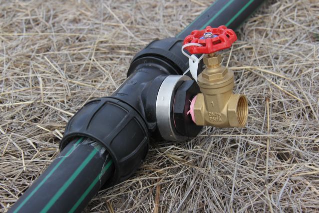
2 inch mainline pipe, with a T-junction and valve to feed off to troughs
Pipes: The top bit
In connecting to the tanks, we initially thought that filling the tanks through an inlet at the top would be most efficient, however, we have since been corrected by our maverick physics advisor Nat. If my understanding is correct, then the water pressure from filling through the base of the tank will actually be less than filling through the top until the water level is equal to the height of the upper inlet. As it is, it fills splendidly through the top inlet, and should we desire, we can opt to fill it through the bottom as well! Since our set-up is based on having a mobile pump that we disconnect after each use, filling through the top inlet could also offer an additional fail-safe to prevent us losing excessive amounts of water from the tanks when we disconnect.

Water in zooms up through the narrowed pipe to the tank inlet. Water out zooms through the valve and out into the troughs or the second tank.

Water flows easily in through the top when filling, out through the bottom when gravity-feeding troughs.
After two days of pipe-wrangling, we finally fired up the pump and, to our surprise, it all worked, filling both tanks simultaneously with a substantial flow. We’ve got the water and the fences. Now all we need are the sheep!

Propping up the fittings with bricks and fitting with a protective cage to prevent livestock damage.
Postscript: Following the advice of Andrew (see comments below) we’ve now propped up the outlet/inlet fittings with bricks to support them as the tank and pipes expand and contract with temperature change. We’ve also used some of the salvaged mesh from around the block to build some rough cages, mostly to deter livestock (and the occasional toddler) from fooling around and climbing on the bits. Stay tuned!
Special thanks to Rob and Pamela for their advice and support, Jeff and Sue for their labour, Nat for his physics insights and Matt, Andrew and Bob for their help.

HI Joel, Sophie (and Asha)
Looking good with the tanks and pipes and stuff…
A couple of thoughts for you:
1. if you add a CHECK VALVE (that is a valve that will only let water though one way) at the outlet of tank between the red isolation valve and the “T” piece, it could help your rig work abit better.
When you start your pump the tank will only fill via the top inlet NOT though the outlet at the base of the tank.
This is because pressure in the pipe, when the pump is running, is greater than the gravity pressure from any water in the tank, forcing the one way check valve to close blocking the outlet.
However when the pump is off the tank will pressurise the line by gravity though the check valve as it currently does.
Iâve got this system setup at home on our tanks and it works quite well from experience
2. Then you can possibly add a float valve to the inlet at the top to ensure that the tank does not get over filled!! This may be an addition for the future if an automated (solar powered) pump is in operation.
3. You may want to support the pipes at the base of the tank by some bricks or something as the weight of the pipes on the tank outlet will, over time, distort or stretch the plastic tank around outlet, especially in summer when the hot weather makes the plastic more pliable and this could lead to a leak or similar problem â¹
4. Also be aware that plastic pipes on the ground in the sun expand and contract quite significantly with changes in temperature, this can lead to fittings popping off if the pipe run is taught when the weather is hot and it then further contracts when it the weather cools down. In other words you want to leave some slack in the line to allow for thisâ¦
There are different types of check valves and i would suggest a “swing” or “flapper” check valves – this type have a spring which means that very little pressure is required to let water through which is good in a gravity feed situation, I might be able to organise one of these for $0, if you likeâ¦
Weâll have to come and pay you a visit sometime at your farm
Warm Regards
Andrew Bennett
BEng (Electrical)
Loudspeaker Designer
[cid:image001.jpg@01CF62F0.36101350]
Krix
14 Chapman Road,
Hackham SA 5163
Australia
T +618 83843433
F +618 83843419
Email: abennett@krix.com
Web: http://www.krix.com
DISCLAIMER:
Krix and the Krix logo are registered trademarks of Krix Loudspeakers Pty Ltd under Australian law. All rights
in this email and any attached documents or files are expressly reserved. This email and any files transmitted
with it are confidential to the intended recipient and may be privileged. If you are not the intended recipient,
please notify Krix immediately. Whilst we have used software to alert us to the presence of computer viruses,
we cannot guarantee that this email and any files transmitted with it are free from them.
________________________________
Hey Andrew, great to hear from you! Thanks so much for your detailed comments and ideas. We’ll definitely put some of them into use as we tweak the design further. I hadn’t considered the weight of the fittings around the outlet in particular, so I’ll look at supporting that further – Asher already is keen to ride the outlet pipes like a horse, so there’s incentive enough! I was also thinking of putting a rough mesh cage around the fittings to discourage curious livestock too. Thanks again, and look forward to catching up soon!
Joel